
Introduction ('Home')
Construction Phase
General Photographs
Pot Furnace Repair Photographs
Pot Furnace Marver Photographs
Small Furnace Construction
Lehr Construction Photographs
The construction phase for the small furnace has been divided into four sections
Superstructure Construction Photographs
Marver Photographs
Pot Setting Photographs
Trench and Wiring Photographs
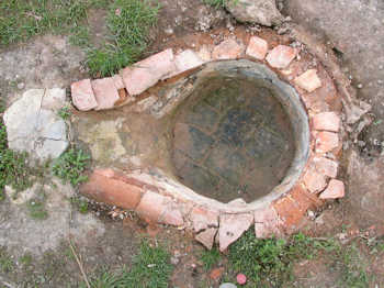
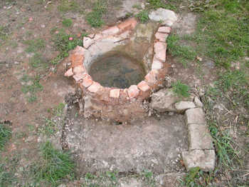
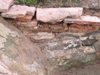
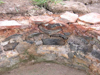
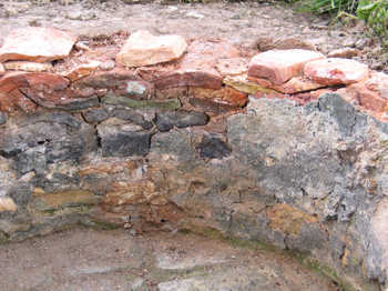
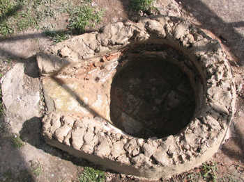
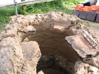
This first set of photographs shows the cleaned fire pit ready for the new superstructure. For more photographs of this stage, see the photographs near the end of this page, recording the demolition of the small furnace.
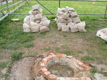
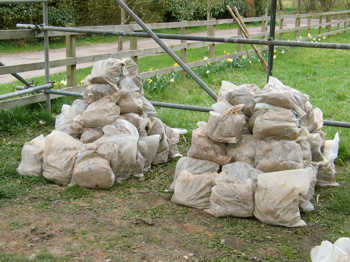
The two piles of bags of daub are for the small furnace and the annealing oven. Each superstructure used an equal amount of daub, 36 bags each, with each bag weighing between 20 and 30kg.
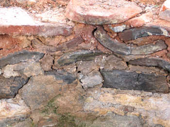
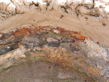
The close ups of the walls show the baked and burnt daub, tiles and stone behind the thin covering of daub, which has been removed. Several of the tiles and stones are blue-black, a colour caused by the reducing atmosphere acting on the iron oxide in the materials.
|
|
|
|
|
|
|
|
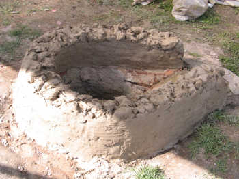
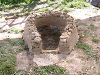
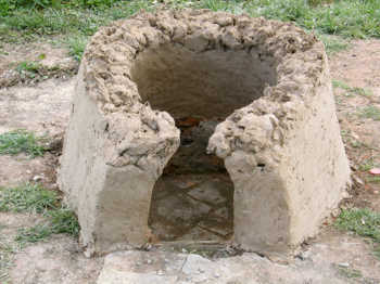
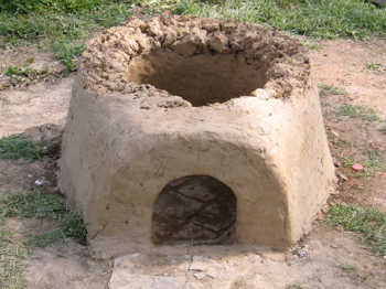
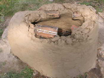
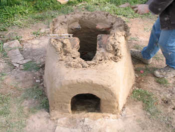
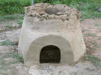
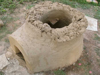
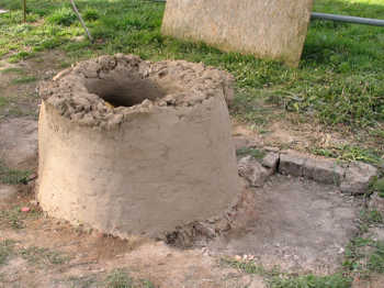
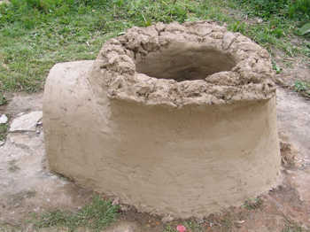
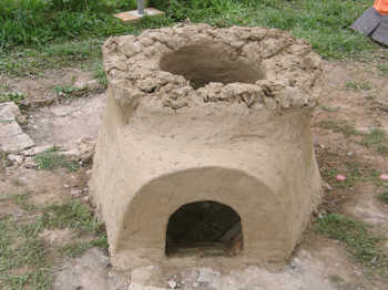
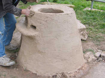
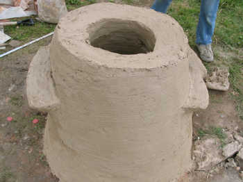
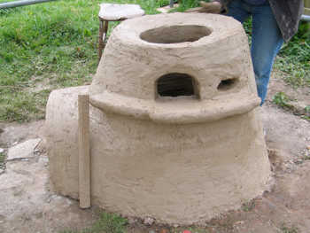
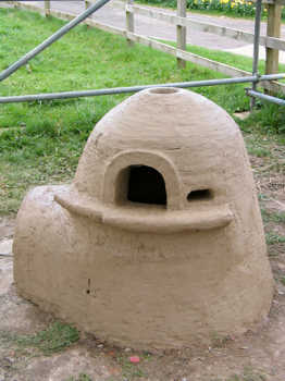
The second set of photographs shows the first 30cm or so of the build, including the stoke hole entrance. The daub has been added by the handful and the walls have been smoothed by smearing a damper daub on the inside and outside.
|
|
|
|
|
|
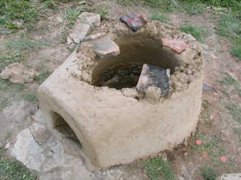
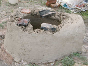
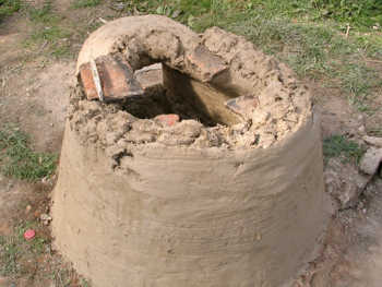
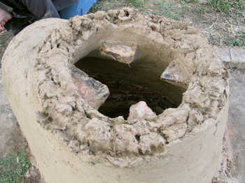
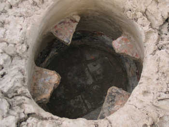
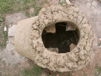
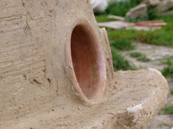
These photographs show the tile fragments being set into the wall, followed by the shelves, which have been formed by progressively widening the wall and shaping the result. The tile fragments will eventually support the shelf for the pot (see this page for the pot sequence). The gathering holes and pipe warming holes are the next features to be added.
|
|
|
|
|
|
|
|
|
|
|
|
|
|
|
|
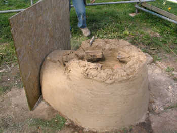
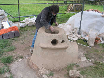
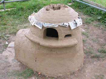
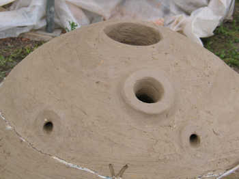
The newspaper separating the domed roof is visible. The roof is built in the same way as the walls, working towards the centre until only a small hole is left at the apex (the 'top hole'). This is very useful as an extra vent during firing.
The short stick in photograph 33 is used to scrape and smooth the walls, in order to create a uniform finish.
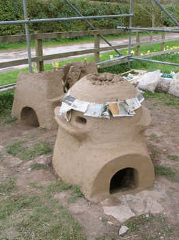
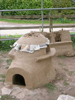
The lehr was built in tandem with the small furnace, and it can be seen in photographs 35 and 36. (See this page for the lehr construction photographs.)
|
|
|
|
|
|
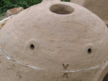
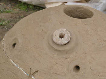
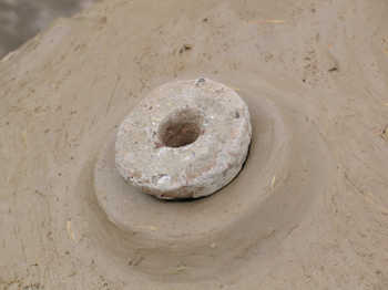
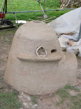
The various holes in the roof include the top hole, the small warming hole (with a fired daub plug, re-used from the previous year), and two small tunnels, through which two metal bars can be passed to lift the roof off the walls. The two 'V's are guide points, used when relocating the roof.
|
|
|
|
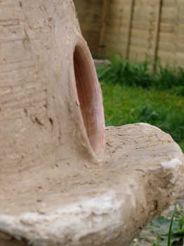
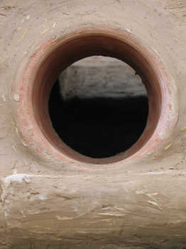
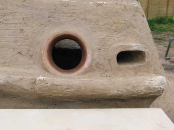
The last set of photographs show the completed gathering and warming holes. Notice the narrower portion of each shelf. These are only used for resting the collars and stoppers, so do not have to be as wide as the portions in front of the gathering holes.
|
|
|
|
|
|
"If you build it, they will come."